 Home
Home
 Back
Back
The J-pole antenna (also known as J antenna) owes its name to its shape resembling the letter J. It was invented in 1909 by Hans Beggerow for use in Zeppelin airships. Typically, J antennas are used in shortwave frequency bands (up to 30 MHz), while radio waves can be used for very long-distance (transcontinental) communications. If you want to know more about frequency, check our frequency calculator.
The J-pole antennas are designed for radio services, maritime communications, international shortwave broadcasting, and worldwide amateur radio. The J-pole antenna is effectively a half-wave antenna that is fed at one end – this is the point where the voltage is maximum, and the current is minimum. There is a very high impedance at this point, which needs to be reduced to a more convenient level using a quarter-wave balanced feed.
The J-pole antenna can be compared to a half-wave dipole fed from the end. Just as a magnet has two magnetic poles, north and south, so in a dipole, we have two electrical poles, positive and negative. Being a half-wave, there are always two opposite poles at the ends of each half-cycle. Hence the name dipole, and each half-wave antenna is, in fact, a dipole. You can calculate its length using a dipole antenna calculator.
In the case of a full wave, the wave will merge if you imagine placing them on top of each other. The feed to the dipole is usually at the center where the cable impedance is about 70 Ω, but you can also feed the dipole anywhere along the beam. This point of a half-wave high-impedance antenna must be matched to 50 Ω in the quarter-wave (λ/4) matching section.
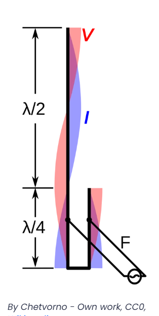
Standing waves of voltage (V, red bands) and current (I, blue bands) on J-pole antenna. By Chetvorno - Own work, CC0, Wikimedia.
The velocity factor (VF) is a parameter describing the speed at which the signal travels in comparison to that of a signal traveling in free space. If the signal travels at the speed of light, its velocity factor would be 1.0, and for one traveling at half the speed of light, it would be 0.5. For example, the velocity factor of a copper wire is set by default to 0.96. You can also calculate the velocity factor of the cable (Vp) as the reciprocal of the square root of the dielectric constant (ε):
Vp = 1 / √ε
The speed factor of the cable is an important parameter, so you can always find it in the data sheets of the coaxial feeder. Otherwise, check out the dielectric constant of the material used in your coaxial cable and type it into the J-pole antenna calculator using the Additional parameters field.
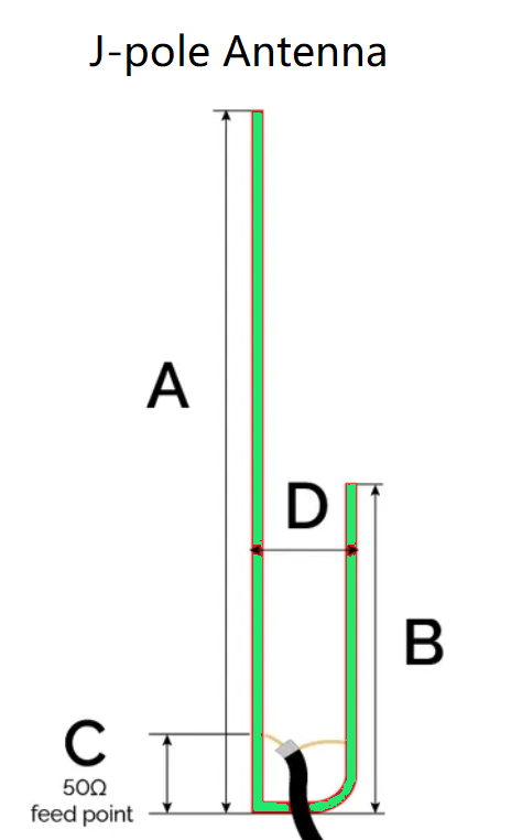
Using the J-pole antenna calculator to build an antenna for a given frequency, you should find the dimensions of the following elements: